
Stabilization using the AT – Pipe Umbrella System: The New Kaiser Wilhelm Tunnel
The Kaiser Wilhelm Tunnel is a railway tunnel that was built from 1875 to 1878 between Cochem and Eller near Koblenz. As the tunnel no longer complies with modern safety requirements, a second tube is being built that will permit access to the existing tunnel via eight connecting structures. With a maximum overburden of 255m and a clear opening cross section of approx. 50m², the tunnel passes through a spur that is known as the Cochemer Krampen.
The new tunnel tube runs parallel and to the east of the existing tunnel with an axis spacing of about 26m. The tunnel length of the new tube measures 4,242m. Along a length of 4,183.6m, the New Kaiser Wilhelm Tunnel is being driven underground using a tunnel boring machine (TBM) with an internal segment diameter of 9m, an external segment diameter of 9.8m and an excavation diameter of 10.12m.
The surrounding ground is part of the Rheinisches Schiefergebirge, which mostly consists of slate and fine sandstone. The tectonically highly affected stratification is cut through by numerous faults parallel to the strata or the cleavage, which are flat to steeply inclined.
During the tunnel drive, there were repeated rockfalls and failures of the face due to the intersection with small to extensive fault zones. The Ø 76mm AT – Casing System was used in order to strengthen the ground locally in the crown and to improve load-bearing capacity.
The system supplied by DSI Austria was a combined pipe umbrella consisting of GRP and steel pipes. The GRP pipes were installed near the TBM shield to prevent jamming of the machine.
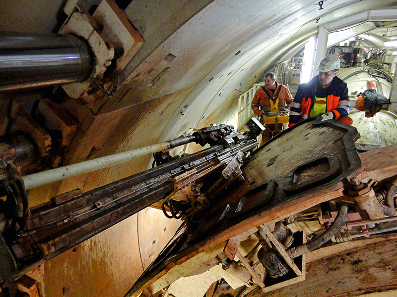
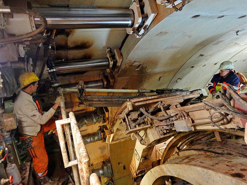
This was done by drilling 17m long pipes through twelve drilling channels in the crown of the TBM with an average spacing of 10° and an inclination of 10° into the surrounding ground. The holes were drilled from the drill carriage that had been mounted on the erector of the TBM.
Each hole contained a starter pipe with an integrated drill bit, three 3m long steel extension pipes, a special transition sleeve in the steel pipe for connecting the GRP pipes and three 2m long GRP pipes. The GRP pipes were primarily installed in the shield area, as it was not possible to ensure the successful dismantling of the pipes above the shield skin in the drilling channel of the TBM.
The GRP pipes were provided at the end of each pipe length, and the hole was drilled deep enough to ensure that all steel parts of the pipe umbrella would be outside the shield skin. That way, the TBM could be operated without interruption after the installation of the pipe umbrella. After the pipe umbrella had been completely drilled, the pipes were fitted with manchette packers at the individual valves and grouted with very fine cement grout.
The fast and uncomplicated installation of the AT – Pipe Umbrella System and its versatile use once again proved itself as an efficient solution to the problems encountered in this project.
